ABOUT EQUIPMENT
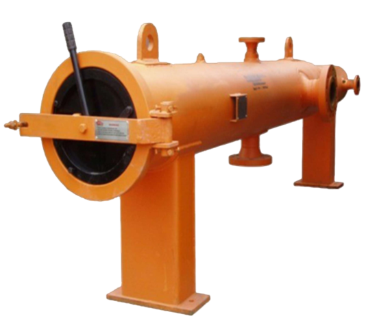
FILTER SEPARATOR
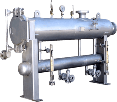
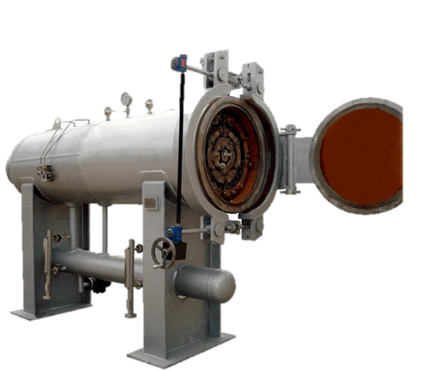
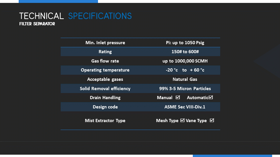
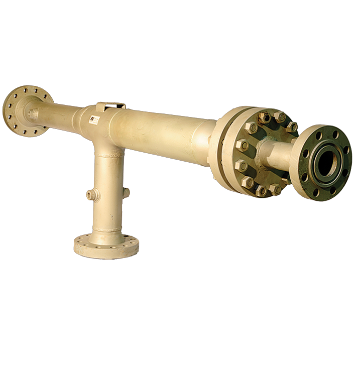
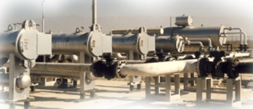
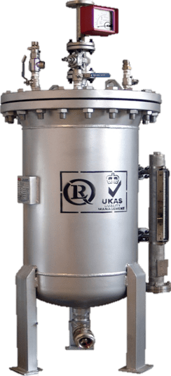
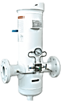
PEPCO Filter separators are available in horizontal and vertical orientations, with horizontal the most common. This type of separator is often used for solids and liquid removal in relatively low liquid loading applications.
Introduction
Principles of Operation
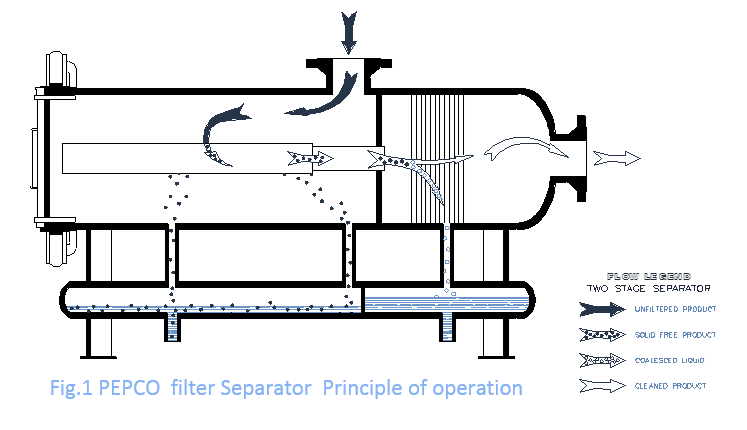
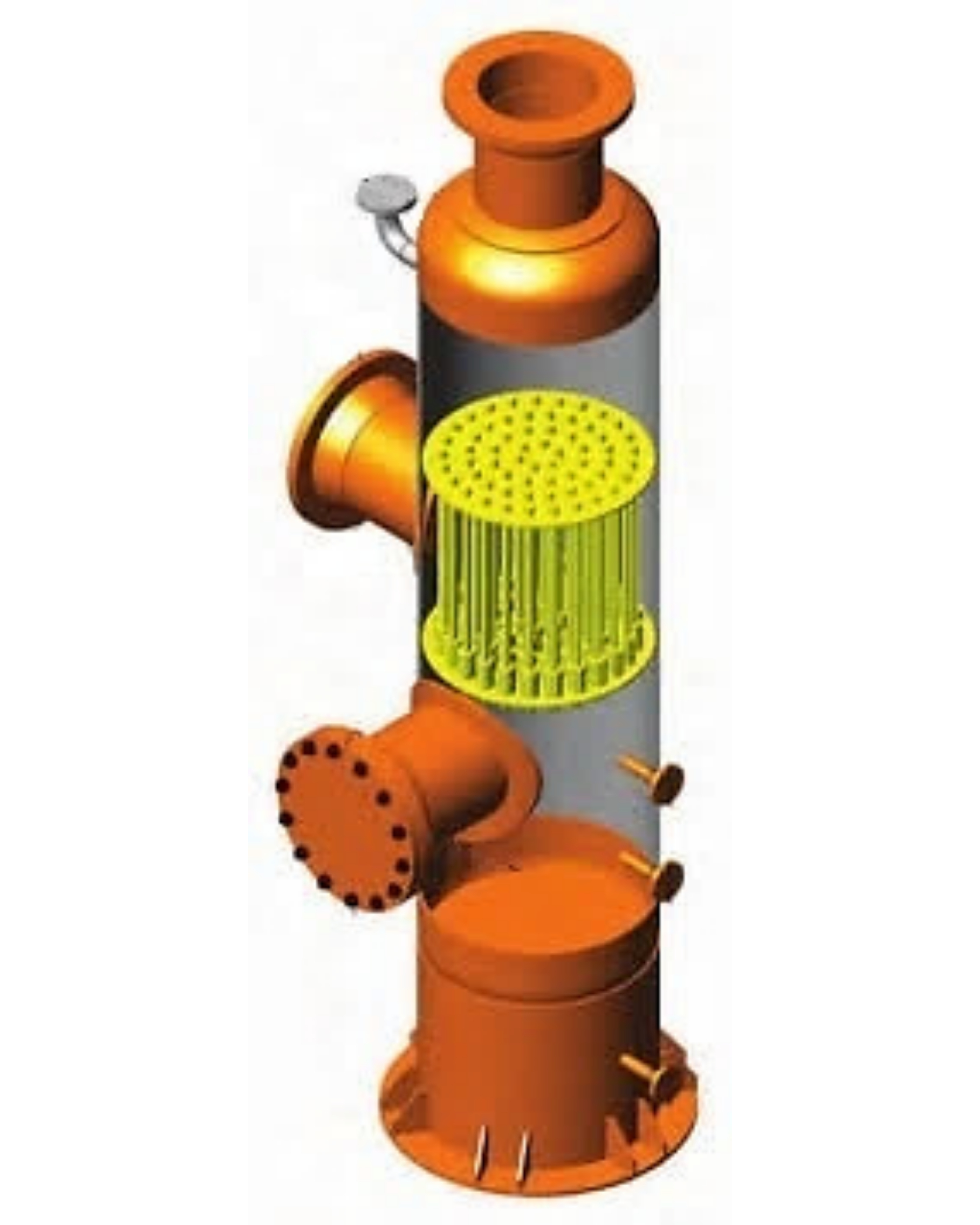
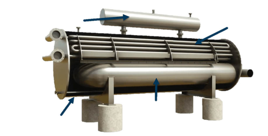
A filter separator is a two-stage device. Gas enters the inlet nozzle and passes through the filter section, where solid particles are filtered from the gas stream and liquid particles are coalesced into larger droplets. Any free liquids are also removed in the first section.
The coalesced droplets pass through the filter riser tubes and are carried into the second section of the separator, where a final mist extraction element removes these droplets from the gas stream. Flow through the filter elements is from an outside-to-inside direction. A pressure drop of 1-2 psi is normal in a clean filter separator. If solids are present, it will normally be necessary to replace the filter elements at regular intervals. A 10 psi pressure drop criteria is often used for filter change out. Removal of the filters is achieved via a quick-opening closure. The second stage of a filter separator contains a mist extraction device. As for a conventional separator this may be a mesh pad, vane pack or multi-cyclone bundle. Mesh pads and vane pack are most commonly utilized. The design of filter separators is proprietary and a manufacturer should be consulted for specific sizing and recommendations.Typical Application
- Distribution systems
- Mainline transmission stations
- Gas gathering systems
- Petrochemical plants
- Reciprocating compressor protection
Vessel Internals
Coalescing Filter Cartridge
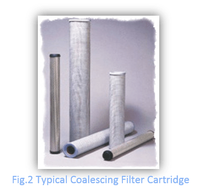
coalescing filter cartridge are used for filter separator where high efficiency removal of oil or water droplets and particulate solids is required. Via a series of graded non-wet table media, droplets are captured, coalesced , and drained to the bottom of the housing, preventing filtered droplet re-entrainment into the downstream gas flow.
Mist Extraction Equipment
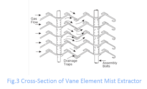
Vane or chevron-type mist extractors (vane-pack) use relatively closely spaced blades arranged to provide sinusoidal or zig-zag gas flow paths.
The changes in gas flow direction combined with the inertia of the entrained liquid droplets, cause impingement of the droplets onto the plate surface, followed by coalescence and drainage of the liquid to the liquid collection section of the separator. Fig. 3 shows a typical vane type mist extractor. Vane packs may be installed in either horizontal or vertical orientations, though capacity is typically reduced significantly for vertical up flow applications.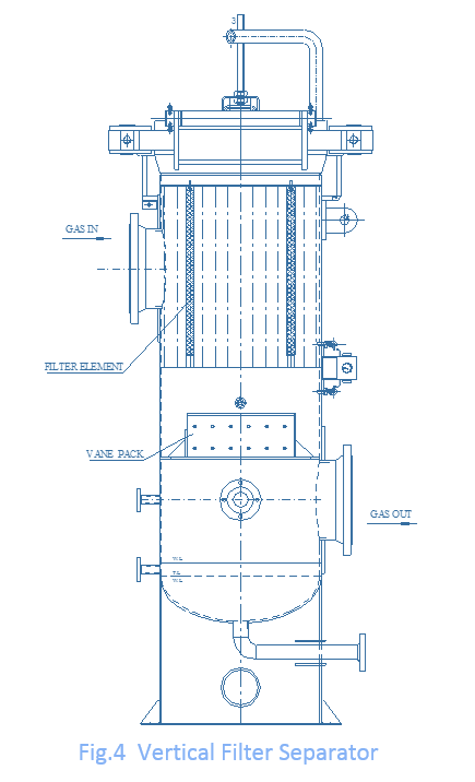
Vanes differ from wire mesh pads in that they typically do not drain the separated liquid back through the rising gas stream. Rather, the liquid can be routed into a down-comer that carries the fluid directly to the liquid holding section of the separator. Vane packs are better suited to dirty or fouling service as they are less likely to plug due to their relatively large flow passages.
A vertical filter separator with a typical vane mist extractor is shown in Fig. 4.
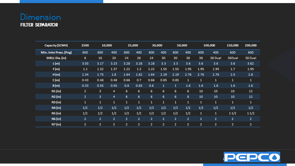
Type Designation

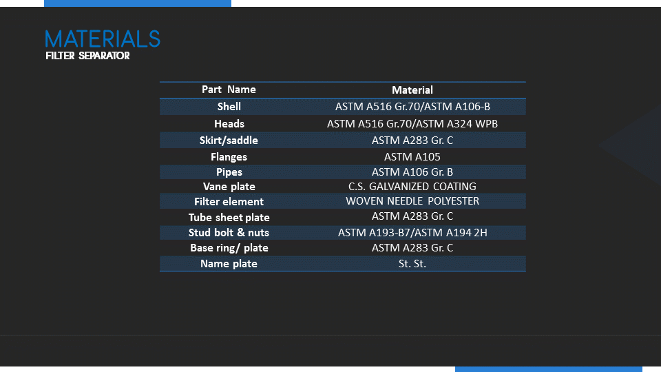
MATERIALS
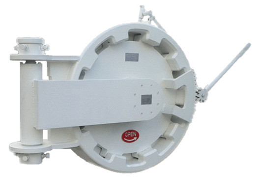
Quick Opening Closure
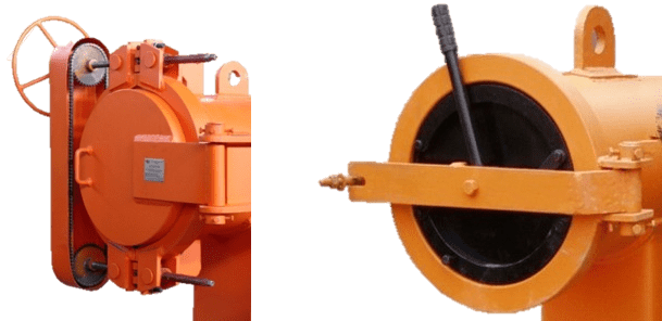
closures provide horizontal or vertical access to filter separator. Our quick opening closures can be operated safely at remarkable speed; any size of closure can be opened or closed by one person in less than one minute, with no special tools required. meet requirements of ASME VIII Div. I The closure hub and door are manufactured from materials that fully comply with the requirements of ASME SEC. II / ASTM and NACE MR 01-75 upon request.
Filter Separator Installation & Maintenance
Installation
- Make sure that all surfaces of flanges are cleaned.
- Fix inlet flange on gas line outlet with nut & bolt and gasket (Inlet and outlet are Showed by arrow on name plate).
- Clean R.F of drain flange and seal it with nuts & bolts and gasket.
Maintenance
- Check the plug valve, it must be closed.
- Open the door.
- Filter elements must be fastened.
- Close the door.
- Check vent valve (ball valve), it must be closed.
- Make sure that filter is fixed on gas station pipe line.
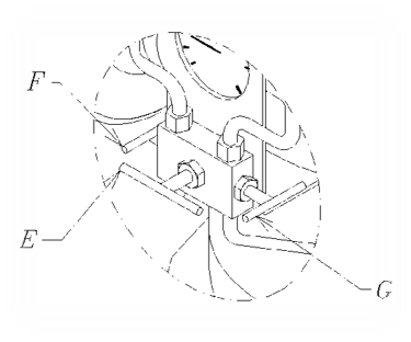
- Open gas line inlet valve slowly. For indicating inlet and outlet differential pressure
- Close “E” valve .
- Open “F,G” valves .
- Open “E” valve, to see differential pressure.
Note: ” Change element filter when D.P.G get 10 psig and it shouldn’t increase more”.

 Contact Us
 Engineering Group
 Creative Strategy
 Download