ABOUT EQUIPMENT
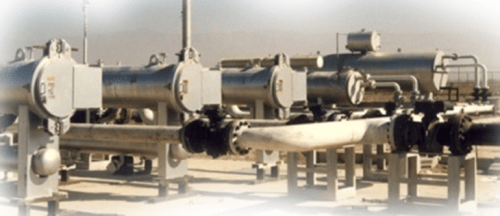
GAS PRESSURE REDUCING STATION
The regulating and measuring technologies in particular play a central role in all pipeline stations. With increasing transport distances and the ever-growing concentration of regional transport networks, the demands on the regulating and measuring technologies increase.
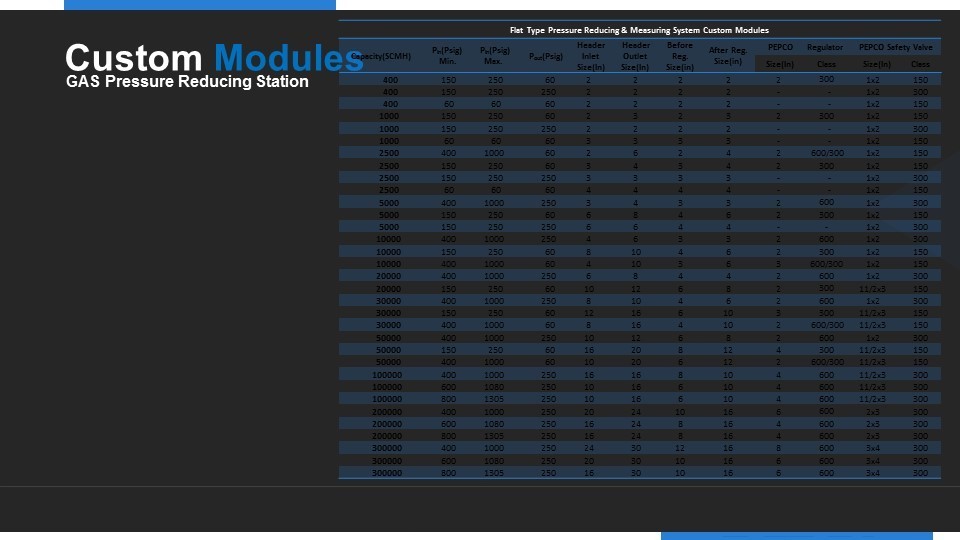
Flat Type Gas Pressure Reducing & Measuring System
The skid-mounted, pre-packaged pressure regulating and metering stations are designed and built to meet individual customer requirements and specifications. PEPCO are a leader in the supply of pressure reducing measuring modules to the gas industry. A combination of experience in both metering and regulating technology allow PEPCO to provide high accuracy, high performance regulating and overpressure protection modules for most applications.
Design Criteria
- All meter tubes should have upstream and downstream isolation valves.
- The insulating joint should be located outside the meter building. If the insulating joint is installed inside a building, an arc prevention device must be installed.
- M&R station piping between the station and tie-in points should be designed to minimize pressure drop and gas velocity, usually less than 20 m/s for runs and 13m/s for headers.
- The safety relief valve should be sized to operate on a 10% of each run capacity.
- Sufficient piping is required between the meter run and regulators or control valves to minimize the acoustic error effects on metering equipment.
- Regulators and control valves should be sized to handle the normal expected range of flows and normal expected range of pressures, at 10% – 90% of valve capacity.
- Depending upon customer requirements, use of fail open or fail-closed regulators and control valves should be determined on a case-by-case basis.
- If noise levels exceed local, state, or federal requirements, adequate measures must be taken to attenuate such noise to the acceptable level. Multiple pressure cuts, heavy wall pipe, pipe insulation, diffusers, quiet trim valves, buildings with insulation, or buried control valves may address this Matter. calculation for the regulating section indicates maximum noise level of 85 dB at a distance of 1 m from the station.
- Isolation full-opening ball valves should be installed upstream and downstream of all regulators and control valves. To reduce turbulence and for sufficient pressure recovery, at least 5 ND of straight pipe upstream and 7 ND downstream should be installed on each run..
- Each pressure control device should have independent sensing lines.
- Regulator capacity shall be based on minimum inlet pressure and specified outlet pressure.
- Consideration has also been given to suppression of turbulent flow conditions on regulation module by designing inlet and outlet header configurations at 90 degrees to operational.
- Safety shut off valve is located upstream of the reducing station.
- The line made up of safety shut –off valve and gas pressure regulator.

- Inlet Valve
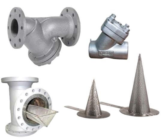
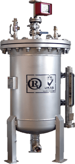
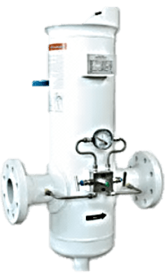
- Gas Filter
- Differential Pressure Gauge
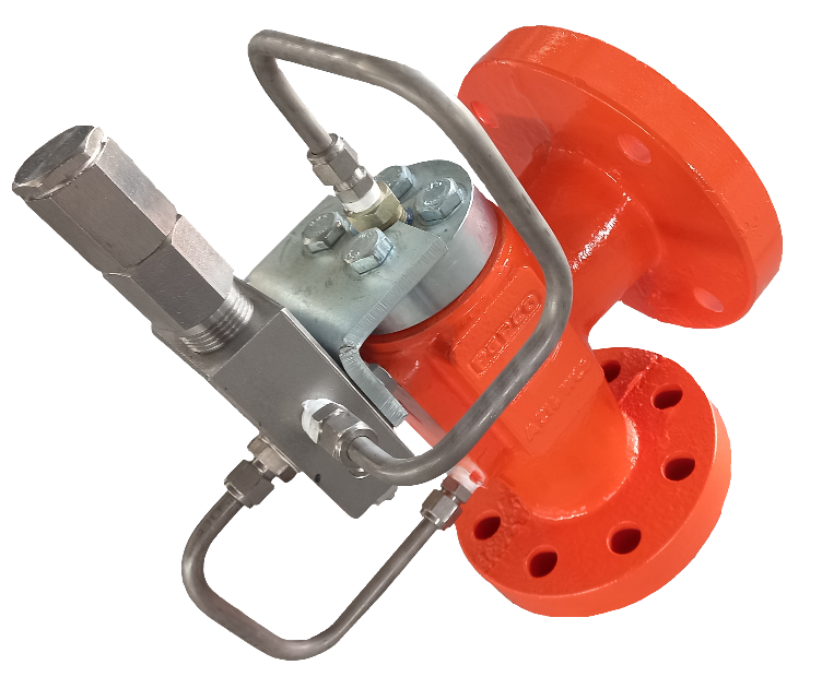
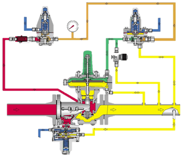
- Gas Pressure Regulator
- Pressure Gauge
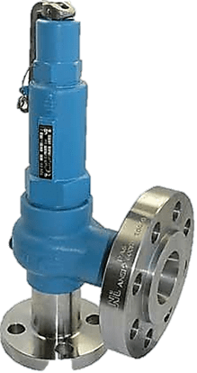
- Safety Valve
- Vent Valve
- Ball Valve after the Pressure regulator
- Safety Shut-off Valve
Station Pipe Sizing
Gas Velocity Limitation
The velocity of gas shall not exceed 20 m/sec in mainline and 13 m/sec in header under the conditions of lowest operational pressure and maximum flow
The equation to determine the gas velocity in a station is obtained as follows:
Us= Qs/A → Qs= Us×A
Where: Us= gas velocity at any section Qs= gas flow rate at any section A= cross sectional area
QSCMH= (14.7×Q(cmh))/(14.7+P(min) )
Where: QSCMH= gas flow rate at standard condition (1 at. & 25°C) (M3/hr) QCMH= gas flow rate at operating condition (M3/hr) P(min)= minimum working pressure(Psig)
The following equation can be used to obtain minimum inside diameter under the condition of lowest operational pressure and maximum flow rate with maximum velocity limitation in pipe.

Where: ID= Minimum inside diameter (mm) C (cmh)= gas flow rate at operating condition (M3/hr) V max= Maximum available velocity in pipe
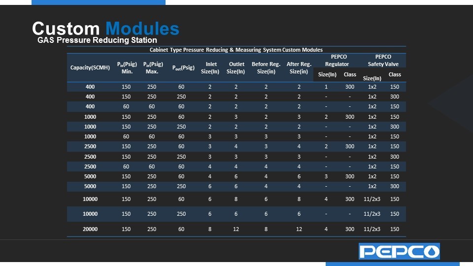
- Cabinet Type Gas Pressure Reducing Measuring System
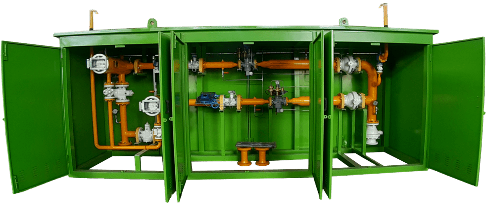
The cabinet gas pressure reducing and measuring series are the standards in medium pressure installations. with flow rates 400SCMH to 20,000SCMH
The cabinet pressure reduction series range offer safe operation and standards compliance in a ready- to- go package. the “folded” design minimizes the space required for the module and the kiosk required to house the module.
Cabinet Type Gas Pressure Reducing & Measuring System
Standard stations are built in two- or multi-line configuration. The one of lines is the reserve line. Both the reserve line and working lines have 100% of the station flow capacity. the reserve line secures working of station and supply with gas in the amount equal to the maximum flow capacity of the station, when working lines are turned off. The line is made up of pressure regulator with a built-in slam-shut valve.

- Inlet Valve
- Gas Filter
- 3-Differential Pressure Gauge
- Pressure Regulator with Slam-Shut Valve
- Pressure Gauge
- Safety Valve
- Vent Valve
- Ball Valve after the Pressure regulator
Operational Functionality
The station must perform the operations that were intended and as indicated in the scope of work. It must function accurately and efficiently. Since measurement facilities operate unmanned, they must function dependably. The design adheres to generally accepted industry standards.
At The design progress we use sound engineering practices. An M&R station design will include engineering disciplines from the civil / structural, mechanical / piping, and electrical / instrumentation sectors.
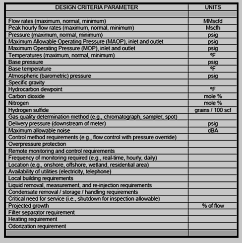
Design Criteria
Equipment cannot be selected or sized without knowing the parameters to which the station is to be designed. While some factors can be assumed, the following table lists most items necessary
Station Piping and Valve Sizing
M&R station piping between the station and tie-in points should be designed to minimize pressure drop and gas velocity, usually less than 50 fps.
Piping and fittings located between the meter run and pipeline should be welded and coated in accordance with specifications.
Piping should be buried wherever possible. The use of screwed piping should be restricted to less than two inch and not buried.
Pipe used for M&R station piping may be sized with Barlow’s Formula: P = [(2 * S * t) / D] * F * E * T P = design pressure, psig S = specified minimum yield strength (SMYS), psi t = nominal wall thickness, inches D = outside diameter (OD), inches
F = design (safety) factor = 0.5 (50% of SMYS) E = longitudinal joint factor T = temperature de-rating factor
When E = 1 for seamless or ERW pipe and T = 1 for 20 – 250°F, then the computation reduces to what is known as the Hoop Stress Equation.
All meter tubes have upstream and downstream isolation valves. The isolation valves are full opening ball valves because, compared to other valve types, they reduce turbulence, pressure drop, noise and grease accumulation in meters and valves. An insulating gasket set should be installed on both ends of the meter tube or tubes between the tube flange and isolation valves.
The insulating gasket should be located outside the meter building. If the insulating gasket is installed inside a building. To balance the station load, all multiple meter tube installations should require upstream and downstream headers.
Note that this equation sizes the header to twice the sum of the cross-sectional areas of the meter runs. In many cases, 1.5 times the sum of the cross sectional areas of the meter runs is sufficient. In addition, the assumption is made that the header outlet nozzles, risers, and meter tubes are all of equal size.
Header type (e.g., T, U, and Z arrangements) is a subject unto its own. Headers should be horizontally oriented. or drains for liquid removal and blow-down.
Sufficient support should be installed under piping to prevent excess stress and strain on the piping assembly.
Metering
The types of meters (primary measurement devices) that are generally accepted in the industry for custody transfer is:
- Orifice
- Turbine
- Ultrasonic
Orifice, turbine, and ultrasonic meters are inferential meters. While orifice meters are non-linear, the others are linear meters. The type of meter selected depends upon the application, range of pressures, and range of flow rates.
Control
Generally, regulators are direct spring-operated or pilot-operated, while control valves require external controllers. Regulators perform pressure regulation, while control valves perform either pressure regulation or flow control. Control valves are for throttling or positional applications, not open-close. The type of regulator or control valve selected depends upon the application, range of pressures, and range of flows. Linear motion control valves are globe body and gate valves. Rotary motion control valves are ball, plug, and butterfly or disc valves. Regulators are usually of the diaphragm or boot style.
Control modes are pressure, backpressure, differential (pneumatic), and flow (electronic) with various combinations of override and under ride. Generally, the attributes of diaphragm or boot style regulators are moderate pressure drop, moderate noise, and moderate capacity. The attributes of ball control valves are low pressure drop, high noise, and high capacity. The attributes of globe body control valves are high pressure drop, moderate to high noise, and moderate capacity.
Appurtenances include pilots, valve actuators, positioners, PID controllers, filter dryers, and catalytic heaters. Valve actuators may be spring and diaphragm or piston type. The use of low bleed or no bleed appurtenances is always recommended.
Sufficient piping is required between the meter run and regulators or control valves to minimize the acoustic error effects on metering equipment. Regulators and control valves should be sized to handle the normal expected range of flows and normal expected range of pressures, at 10% – 90% of valve capacity. If this condition cannot be met, additional parallel control valves can be added using split range control. This arrangement can also improve low flow performance. When designing pressure regulation, each cut should not exceed 250 psig. The gas temperature will cool approximately 7º F per 100 psig drop in pressure (or 1º F per 15 psig drop in pressure). If necessary, adequate heating facilities should be installed to prevent regulator freezing.
Depending upon customer requirements, use of fail open or fail-closed regulators and control valves should be determined on a case-by-case basis. If noise levels exceed local, state, or federal requirements, adequate measures must be taken to attenuate such noise to the acceptable level. Multiple pressure cuts, heavy wall pipe, pipe insulation, diffusers, quiet trim valves, buildings with insulation, or buried control valves may address this matter. Piping velocities should be limited to a maximum of 100 fps.
Installation Criteria
The figure below shows some typical installation of devices. all equipment’s are normally installed horizontally. tap lines should be connected to a turbulence free outlet pipe segment at a minimum distance from the regulator of 5 times of nominal diameter of the downstream pipe.
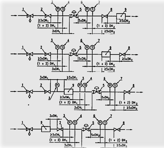
- Shut-off device to prevent overpressure, if necessary
- Inlet full bore valve
- Inlet pressure Indicator
- Inlet temperature Indicator
- Regulator under test
- Outlet pressure indicator
- Outlet temperature indicator
- Flow rate regulating valve
- Flow meter
- DN1 = nominal diameter of the upstream pipework connected to the regulator under test
- DN2 = nominal diameter of the downstream pipework connected to the regulator under test

 Contact Us
 Engineering Group
 Creative Strategy
 Download