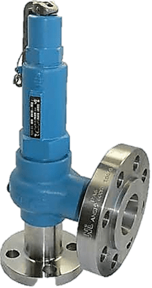
ABOUT EQUIPMENT
SAFETY RELIEF VALVE (S.R.V)
A Safety Relief Valve is a safety device designed to protect a pressurized vessel or system during an overpressure event. An overpressure event refers to any condition which would cause pressure in a vessel or system to increase beyond the specified design pressure or maximum allowable working pressure (MAWP).
DESCRIPTION INTRODUCTION
A Safety Relief Valve is a safety device designed to protect a pressurized vessel or system during an overpressure event. An overpressure event refers to any condition which would cause pressure in a vessel or system to increase beyond the specified design pressure or maximum allowable working pressure (MAWP).
The primary purpose of a Safety Relief Valve is protection of life and property by venting fluid from an over pressurized vessel.
Many electronic, pneumatic and hydraulic systems exist today to control fluid system variables, such as pressure, temperature and flow. Each of these systems requires a power source of some type, such as electricity or compressed air in order to operate. A Safety Relief Valve must be capable of operating at all times, especially during a period of power failure when system controls are nonfunctional. The sole source of power for the Safety Relief Valve, therefore, is the process fluid.
Once a condition occurs that causes the pressure in a system or vessel to increase to a dangerous level, the Safety Relief Valve may be the only device remaining to prevent a catastrophic failure. Since reliability is directly related to the complexity of the device, it is important that the design of the Safety Relief Valve be as simple as possible.
The Safety Relief Valve must open at a predetermined set pressure, flow a rated capacity at a specified overpressure, and close when the system pressure has returned to a safe level. Safety Relief Valves must be designed with materials compatible with many process fluids from simple air and water to the most corrosive media. They must also be designed to operate in a consistently smooth and stable manner on a variety of fluids and fluid phases.
SPRING LOADED
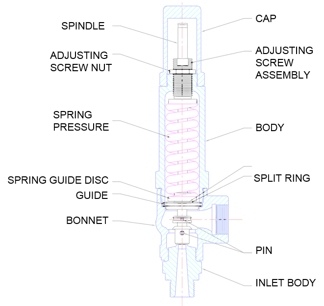
A spring loaded safety valve includes a control device which admits the pressurized medium to a supplemental loading system which consists of a spring housing which serves as a cylinder for a spring retainer which serves as a supplemental loading piston that is arranged about two adjustable sleeves which are arranged around the valve stem and which control the response pressure and the supplemental loading of the valve spring.
Design of Safety Relief Valve
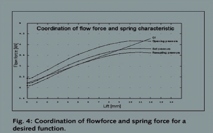
The development of a new series of API safety relief valves is only possible following extensive investigation into fluid flows. This paper describes how a new method of “ Flow force ‐ Characteristic ‐ Measurement ” facilitated extensive review of the quality of the shape of all parts in the flowing area and enabled parts to be optimized. Further, a world‐class test facility enabled verification of the required characteristics for a larger range of pressures and sizes than needed for an ASME certification. In addition to these measurements,
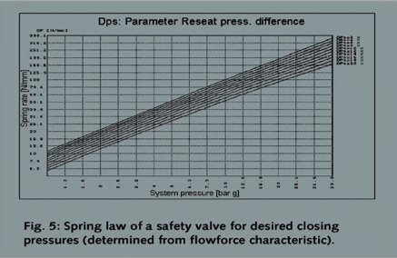
special flow calculations provided information about local fluid dynamics. Components in the flow area could therefore be optimized with high accuracy. This has resulted in a new series of API safety relief valves with ASME and TÜV certification, providing significant advantages for end users.
Relation between flow force and spring force is very important to designing safety relief valve In these pictures you can find some diagram that can help us to choose suitable spring in safety relief valve.
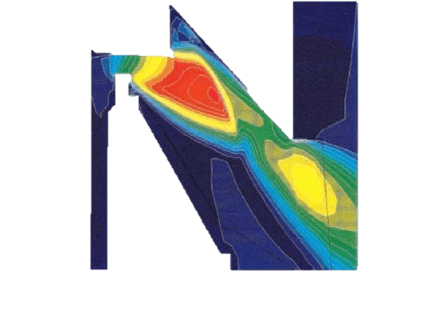
We can also simulate fluid flow inside of safety relief valve by a suitable C.F.D method An essential role in this optimization process was played by numerical calculations of the flow field in the safety valve with a CFD program system according to the Finite Volume Method. The calculations were carried out for three‐dimensional compressible and non‐compressible flow.
The procedure was carefully checked by means of flow shapes known from the literature. Finally, these calculations were confirmed very well by comparison with experiments with compressible supercritical flow at a plane valve model
Detail of the compressible supercritical flow between the valve seat and the shape of disk and lifting bell.
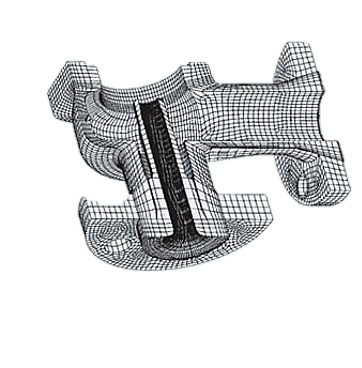
Flow inside of safety relief valve simulated by finite element method. in finite element suitable grid is very important and you can see this grid in picture.
Cross linkage of the API safety valve body for the Finite Element Measurement calculation
Safety valve series are proved with air, saturated steam and Natural Gas in accordance with the requirements of ASME VIII in the course of a product approval. These tests are carried out on behalf of ASME by the National Board (NB) in Columbus, Ohio, in the USA. The results are published for every safety valve in the so‐called “Red Book” with the title “Pressure Relief Device Certifications”. This document gives information which safety valves are certified with which pressure range and for which flow quantities, e.g. according to the requirements of ASME VIII or of the size of the current nozzle diameter do and the allowed discharge coefficient Kd, respectively
There are only very few manufacturers world‐wide who cover the performance range of the API 526 with their safety valve program, have the approval according to ASME VIII and are certified in accordance with the National Board and may identify every API safety valve with the UV Stamp and the indication NB on the nameplate.
After the Bopp & Reuther API 526 safety valve series Si 81/83/84 (Figure 1) was approved in this manner in 1995 the same series was also TÜV type test approved with the type test approval mark BKZ 1006 [3]. This TÜV‐approval also permits utilization of this safety valve according to the API Standard in systems where a TÜV approval is required.
Relief system is more than a safety relief valve or rupture disk; it includes:
- backup relief device
- line leading to relief device
- environmental conditioning of relief device
- discharge piping/header
- blowdowndrum
CALCULATIONS
Determine Relief Vent Area
Gas and vapor sizing:

- A: Minimum required effective discharge area, square inches.
- C: Variable factor, depending upon ratio of specific heats(k=Cp/Cv).
- Kd: Effective coefficient of discharged =0.975 when a pressure relief valve is Installed with or without a rupture disk in combination.
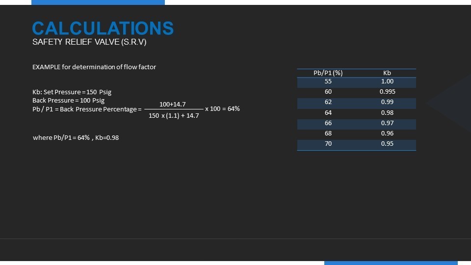
- Kb: Capacity correction factor due to back pressure for conventional and pilot operated valves use a value for Kb equal to 1.0
- M: Molecular weight og the gas or vapor obtained from standard tables.
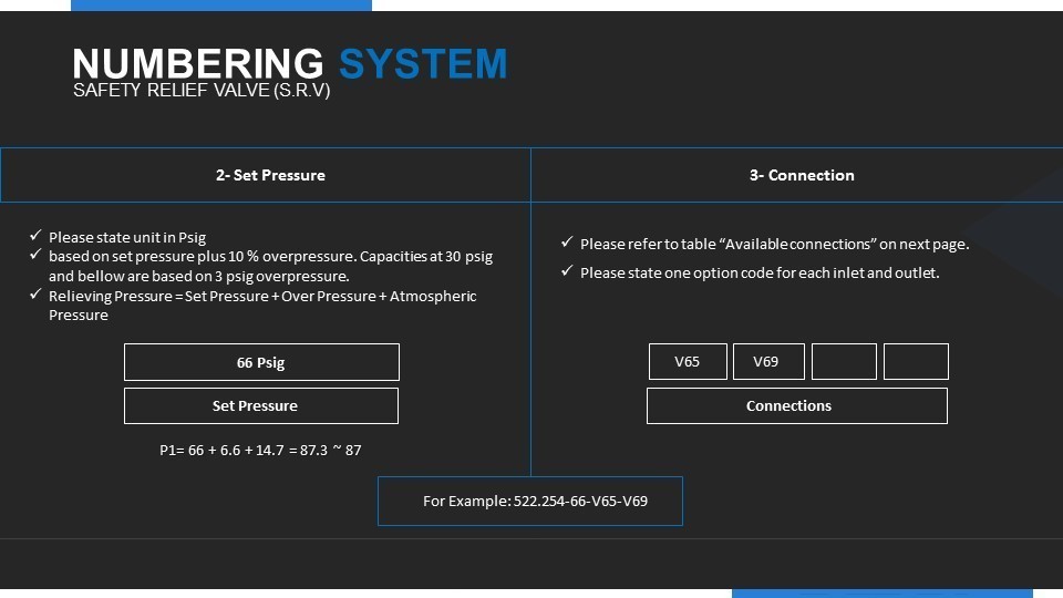
- P1: Relieving pressure in pounds per square inch absolute. this is Set pressure + Over pressure + Atmospheric pressure
- T: absolute temperature of the fluid at the valve inlet(F+460)
- Z: Compressibility factor. Use Z=1.0 If valve is unknown.
- G: Specific gravity of the gas and vapor at flowing conditions.
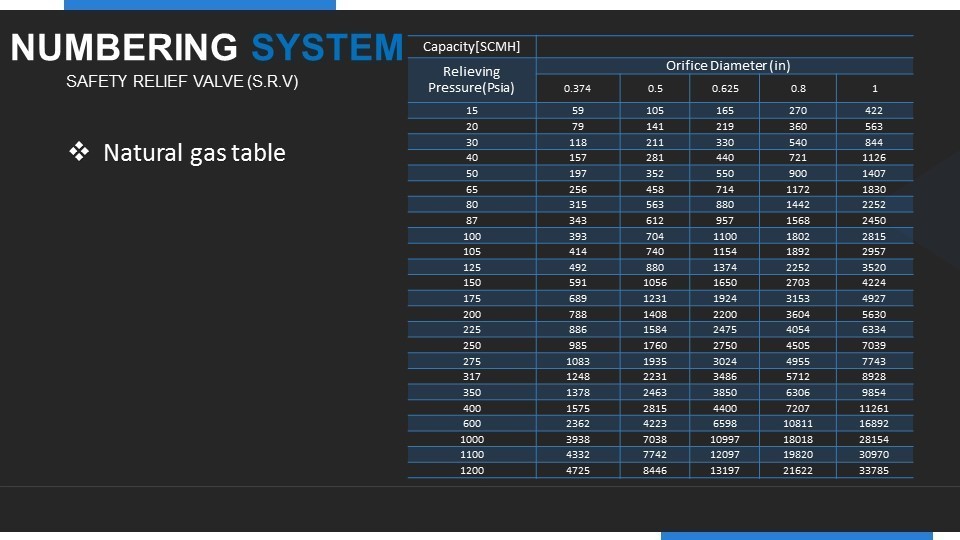
- Q: Required relieving capacity in standard cubic feet per minute.
Sizing Correction Factor and Multipliers
- Flow Factor for Vapors and Gases – Kb for Back Pressure Exceeding Critical
Back Pressure generally has no effect on the set pressure or flow capacity of PEPCO pilot operated pressure relief valves except when flow is expected to be subcritical (absolute back pressure exceeds 55% of the absolute relieving pressure). in this case the flow correction factor Kb must be applied.
Note: Consult the factory for back pressure greater than 70% of set pressure.

LIQUID SIZING
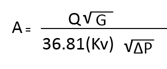
A: minimum required effective discharge area, square inches. Q: Required relieving capacity in gallons per minute at flowing temperature. ∆P: Differential pressure (PSI). this is the set pressure + overpressure – back pressure Kv= Flow correction factor due to viscosity of the fluid at flowing condition.
Note: The minimum required effective orifice area shall be determined in accordance with API 526, part I.

 Contact Us
 Engineering Group
 Creative Strategy
 Download