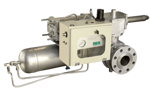
ABOUT EQUIPMENT
SAFETY SHUT OFF VALVE (S.S.O.V)
A safety shut-off valve is used in industries such as those that handle industrial gases. The role of this safety valve is to detect if there is trouble in the system, causing the opening of an electrical circuit. When the failure in the system has been corrected, the circuit is closed and the valve is opened through the action of a lever. However, when the failure has not been corrected successfully, the circuit remains open and the lever on the valve does not work.
Introduction
The PEPCO Pressure Protection System Is Designed to Protect Equipment Downstream of a Pressure Reducing Station in A Gas Distribution System.
It Consists of a Trunnion Mounted Ball Valve Complete with Actuator and Control System Supplied in A Self Contained and Compact Unit. It Is Installed in Pipeline Upstream of the Pressure Reducing Station.
If There Is an Excessive Change in Pressure Downstream of the Station Due to an Equipment or Operational Malfunction, It Will React by Shutting Off the Supply of High Pressure Gas, The Pressure Switch Can Sense Either Rising Pressure, Falling Pressure or Both as Specified.
Simplicity, reliability and economy being at the top of the list of design parameters.
- Designed to be used in natural gas pressure reduction stations for safety purpose.
- Work with pressure of line.
- Upon request, it can be used for different fluid by operating with an external gas pressure source.
- Valve is a complete package with actuator and control system.
- It can adjust to the requested values for #150 #300 #600 pressure classes.
- It can modify for different climate and site conditi.
- According to API Design Standards (API6DX)& IGS –M-IN-301.
- System Sensitivity 2% ± set point.
- Precaution for dirty gas and Power Deficiency.
- Remote signal.
- Pressure ranges according to customer request.
- Special material according to customer request.
- Application with different valve type.
- Failsafe options.
PARTS OF PRODUCT
- Ball Valve(PARTS)
- Actuator(PARTS)
- Gear Box
- Pneumatic Jack
- Control System( PRODUCT)
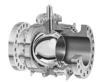
- BALL VALVE
- ITrunnion mounted or floating type.
- Two piece or three-piece construction.
- Double block and bleed in open and closed position.
- Antistatic device.
- Sealant injection.
- ACTUATOR
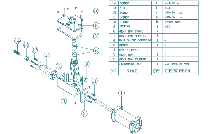
- Double acting scotch yoke.
- Designed for one million operations in normal working conditions.
- Yoke optimized design to give increased torque output in breakout / reseat position.
- Low friction self lubricating PTFE piston seals as standard.
- Nickel a steel alloy drive shaft and hardened steel alloy assembly (sg on largest model).
- All bearing surfaces lubricated for life.
- Lapped and anodized cylinder bores.
- Acetalic resin drive shaft bearings (bronze on larger models).
- Anodized actuator cylinders and end caps to prevent external corrosion.
- The actuator of the scotch yoke design powered by pneumatic cylinders.
- The scotch yoke design ensures maximum torque output when the actuator is either opening or closing the valve.
- The yoke, drive pins and drive shaft are manufactured in alloy steel suitably treated.
- The piston and cylinders are manufactured in aluminum alloy and fitted with low friction self lubricating seals.
- On larger models the body and scotch yoke are in ductile iron with bronze bearings.
- The bores are honed and hard anodized to improve efficiency and internal corrosion resistance.
- The actuator body cylinders and end caps are anodized and painted to prevent external corrosion. On larger models the end caps are in steel.
- CONTROL SYSTEM
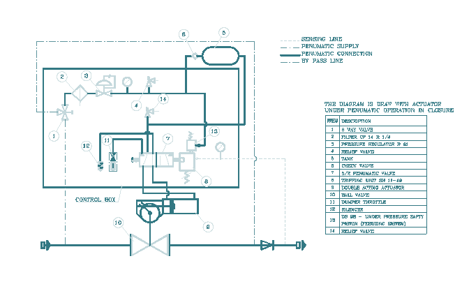
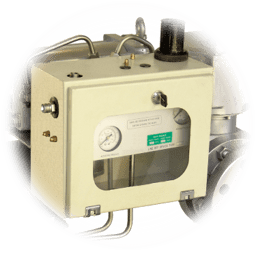
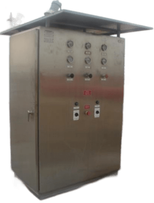
- The actuator is fitted with the shut off system.
- The system is complete with remote and local control facilities.
- The remote facility is via a pressure switch.
- The pressure switch can sense either rising pressure, falling pressure or both as in the data sheet.
- On receipt of a rising or signal the system will close the pipeline ball valve.
- Local control is selected via the 3 way ball valve.
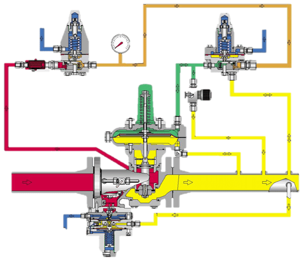
- A 3-way ball valve is used to supply the system with upstream power gas. it is also used as a by pass to equalize the pressure across the pipeline valve before reopening.
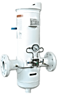
- The inlet power gas is filtered through a cartridge filter.
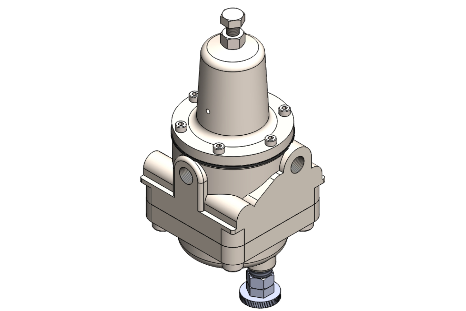
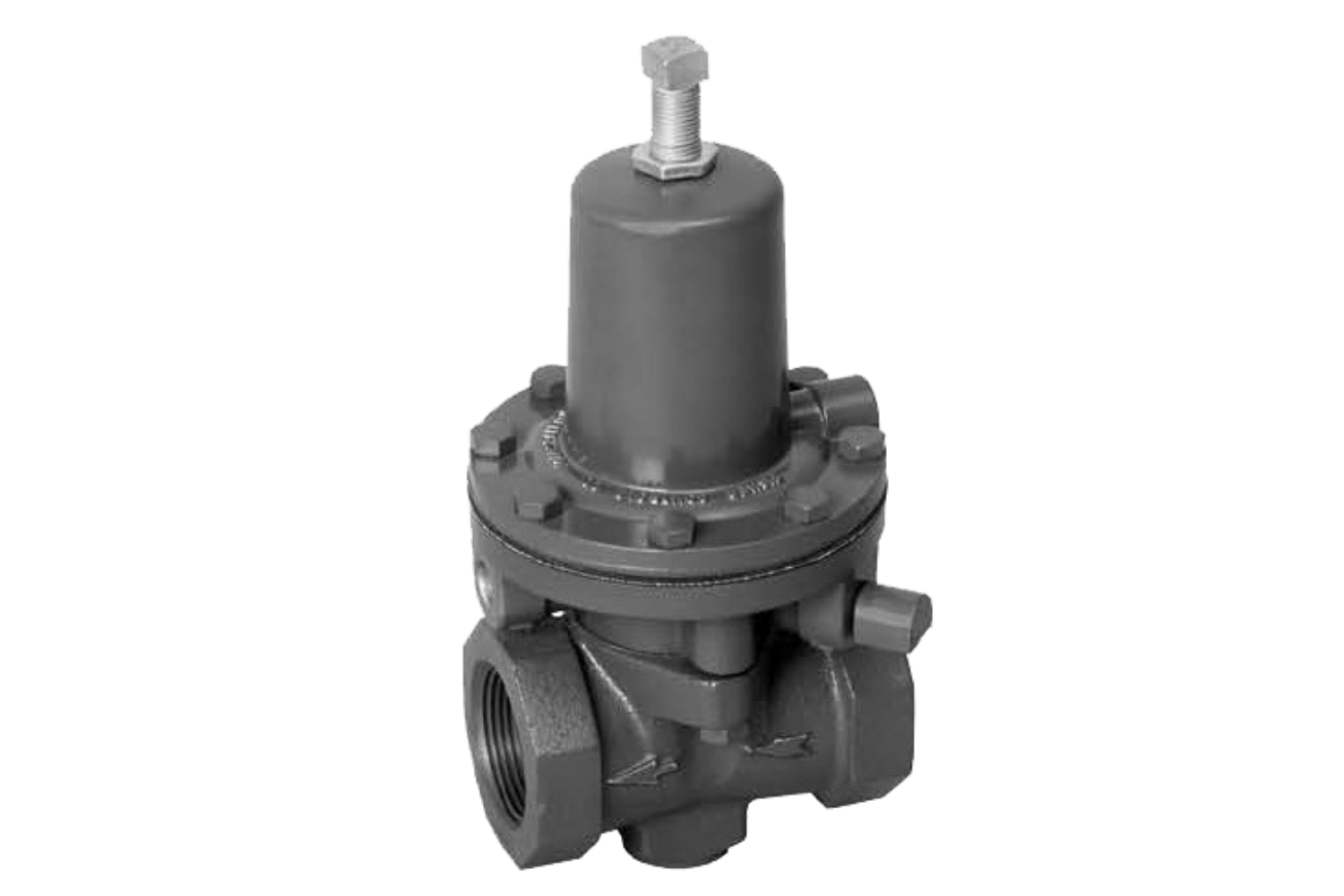
- The gas pressure is then reduced via a pressure regulator to the set pressure stead on the schematic drawing.
- The outlet gas pressure is monitored using a pressure indicator.
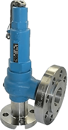
- The regulator is fitted with a pressure relief valve to protect equipment on the output side of the regulator.
- The pipeline valve can only be re-opened when the down stream pressure has returned to a safe normal pressure and the dc is physically reset at the cabinet.

 Contact Us
 Engineering Group
 Creative Strategy
 Download